Floor plan to 3D, four ways: which of these agents build a building model, and which build a picture of one
mdjsonmcp2026-11-16 · 25 min · bim · cad · 3d · mcp · agents · rust · threejs
A 2:17 narrated explainer, drawn in code. Every number and picture in it is this article's own; the sources are below.
› transcript
An agent got the drawings for an eight floor hotel. This came back. The post calls it the full BIM model. What does that mean? Hi, I'm Jamb! Four tools turned floor plans into buildings this week. Let's sort them by what comes out. DWG sheets into a hotel. A plan image into a flat. A vector PDF into a barn. All of it looks like 3D. It is not the same kind of thing. A plan is a cut through the building, looking down. It gives footprints, thicknesses, and openings. It gives no heights. So every tool fills them in: a default, a setting, a prompt, or a guess. A building model cuts each door and window into its host wall, with a sill and a lintel. Trace the plan from pixels, and a door is a break in a dark band. Short gaps become solid wall. A wide one leaves a hole from floor to top. Either way, the openings are gone. Snaptrude's typed request is one line. The brief behind it gives the storey heights: three point four and four metres. Its two questions are ones a plan cannot answer. It claims IFC. The demo never opens one. Interior AI says it plainly. Sizes are estimates. One floor only. The barn tool reads the vector drawing. Each storey has a ceiling height and a slab. French plans write each opening's height on the sheet, so it reads that too. Walls are layered build-ups with R values. The richest model here, and no export yet. 3d-new-era-ai is open source, so I ported its wall tracer and ran it on levelsio's plan. Every door became wall. And the glassy living room walls vanished, the same ones Interior AI missed. So what comes out? Snaptrude claims IFC. Interior AI gives you a scene to walk and paint. The barn tool, nothing yet. 3d-new-era-ai keeps real walls inside, and exports one mesh. Every plan to 3D tool invents the vertical half. Ask where each height came from. No heights on a plan, doors traced into walls, and one IFC claim to check. Thanks for watching! Every source is in the full article. I'm Jamb. Bye!
Why read this
Solidtop 85%Sorts four plan-to-3D tools by what they output: BIM elements, a mesh or a render. Reads the open one's source and ports its wall tracer to test it.
- Original analysis
- Concrete numbers to act on
- Explained from first principles
3D & spatialRuns on a laptop CPUMixed licencesPractitioner roundup
How this was scored
- Is it new?
- 1 of 3: An incremental tweak
- Can I trust it?
- 2 of 3: Measures key facts from files, code or configs
- Can I run it?
- 1 of 3: API-only, gated or restrictive licence
- Will I understand it?
- 2 of 3: Mechanism from first principles with figures
- Can I act on it?
- 2 of 3: A concrete recipe, numbers or comparison
- Will it last?
- 1 of 3: Relevant for months
- Does it affect many?
- 1 of 3: A specialist community
- Only here?
- 2 of 3: A teardown or measurement few others did
Score 56 of 100, ranked 560 of 748 rated articles. Each question is answered 0–3 by hand, and a 3 is rare. How articles are scored
Between 12 and 14 November four posts went past that all showed the same trick: a 2D plan goes in and a 3D building comes out. Snaptrude gave its agent "the DWGs for an 8-floor hotel and one prompt" and got "the full BIM model". levelsio showed Interior AI 3D working from "just" a floor plan. Romain Briaux showed a tool where you edit the plan in 2D, see it in 3D, and layer insulation, plumbing, ventilation and electricity on top. And dextune posted 3d-new-era-ai, an open-source home design editor that MCP clients drive.
I build drawings-to-BIM and scan-to-BIM systems for a living (Revit driven over MCP from drawing sets, and point clouds turned into elements that compile to IFC), so "plan to 3D" makes me ask what comes out. BIM elements: a wall that knows its axis, thickness, height, storey and type, a door that knows its host wall, in a file someone else's software opens intact. A mesh: triangles you can walk through and paint, but cannot ask how thick the north wall is. Or a picture of a model, which is fine for a client meeting and useless after it.
For each tool I asked what it produces, how it gets walls, openings and storeys out of the drawing, and where it would fall over on real drawings. Only one has source code. For the other three I keep what a video frame or the author's reply shows apart from what the vendor claims.
What a plan sheet holds, and what a wall needs
A floor plan is a horizontal cut through a building about a metre above the floor, looking down. The cut shows wall footprints (axes, thicknesses), door swings and window symbols (positions, widths), and room outlines. It shows nothing vertical. Wall heights, sills and heads, slabs and storey elevations live in sections, elevations and schedules. A wall's construction lives in a legend. Which storey a sheet is comes from its title block.
An IFC wall needs all of it. IfcWall has a placement and an extruded body, so it needs a height. It sits in an IfcBuildingStorey with an elevation. Its thickness is properly the sum of an IfcMaterialLayerSet on its IfcWallType. A door is an IfcDoor that fills an IfcOpeningElement that voids a specific wall, so the door has to know its host. Half of those fields are not on a plan at all.
So every plan-to-3D tool fills the vertical half from somewhere: a default, a setting, the person's prompt, or a model's guess. That source separates these four tools more than the 3D view does.
Every one of them reads the plan-shaped fields and gets the vertical ones elsewhere: Snaptrude from the prompt, the barn tool from per-storey settings, 3d-new-era-ai from defaults, Interior AI from its model. Nobody here reads a section.
Three ways to get walls out of a drawing
Read the vector entities. A DWG, or a PDF exported from Archicad or Revit, already holds lines. A wall is two parallel lines with a hatch between them on a layer like A-WALL; pair them, take the midline as the axis and the spacing as the thickness. Doors are often named blocks. It still breaks: layer names are whatever the drafter chose, exploded blocks turn a door into loose arcs, and furniture on the wall layer pairs up into phantom walls.
Trace the pixels. A scan or flattened PDF has no entities, so you threshold it and look for thick dark bands. That works for solid-filled walls only. Hatched walls read as stripes, thin-line walls as nothing, and a door is a break in the band that the tracer must tell apart from a wall's end.
Let a model look at it. A vision model copes with hatching and odd symbols and guarantees no single coordinate. A wall it puts at 3.6 m may come from a dimension string, a guessed scale, or nowhere. The image-to-DWG skill tags every value as known, scaled, inferred or unreadable, the only design here I have seen that tries.
Once you have walls, extrusion is easy. The widget extrudes one small plan two ways. In element mode doors and windows are hosted objects and the heights are defaults. In traced mode the plan goes through 3d-new-era-ai's tracing rule, covered below: a gap no wider than max_gap (130 cm by default) becomes solid wall, and a wider one leaves a hole from floor to top.
Drag the storey height: nothing on the plan changes, because that number is not on the drawing.
Snaptrude Agent: DWGs in, a hotel out, and a long brief in between
Snaptrude is a browser-based design and BIM tool. AEC Magazine covered the Agent's launch on 29 October as an agent that takes teams "from early concept studies to construction-ready LoD 400 models". The 12 November post is the CAD case: "Turning CAD plans into BIM usually means tracing every floor again. We gave Snaptrude Agent the DWGs for an 8-floor hotel and one prompt. It asked a couple of questions, then built the full BIM model. Every element stays editable."
The post carries a 67-second video. I stepped through it.
Eight sheets land on the canvas as one object the properties panel calls a "Cad Sketch". The typed request is one line: "Use the imported DWG and create a detailed model based on it." Then the chat shows the message the agent actually works from, a long brief whose top is scrolled out of view. The visible part includes "Levels 3 to 6, 3.4 m each" and "Level 7, 4.0 m", surface parking "for about 25 to 30 cars", three sports courts, a hex colour for each department, and the instruction "Trace every room from the DWG at its true size and shape, including curved walls and the fan-shaped wings, and keep cores aligned from Lower Ground to Level 7." It ends with a work plan: "scale check and floor mapping, then Lower Ground, then Ground, then Levels 1 and 2, then one typical floor checked before copying it to Levels 3 to 6, then Level 7, then the site layout."

The questions are good ones: how the circular lobby relates vertically to the Level 2 executive lounge ring (a void through two floors is a section question), and where the hotel sits on the 40,731 m² site relative to the north-east road. A person modelling from these plans would ask both. Then the video cuts to the finished model, in a file titled "Hotel 104 - BIM build".
What the demo shows. DWGs in, storey count and heights from the prompt, a staged plan, clarifying questions, and a coherent-looking building whose window title says BIM.
What Snaptrude claims elsewhere. Its comparison page says "Parametric BIM. Walls, slabs, columns, doors, windows, rooms with defined types and properties." and "Native IFC 2x3 and IFC 4. No plugin." Its homepage offers an example prompt, "Recreate this uploaded CAD floor plan as an editable model, including walls, doors, windows, and room boundaries."
What I could not verify. The video never selects an element, opens a property panel or exports a file, and the cut hides how long the build took and how the curved walls became elements. The same comparison page describes DWG import "as a trace-over underlay", and the help article on importing CAD describes a manual workflow: assign the plan to a storey, then "The Draw tools automatically snap to the CAD plan." So the documented path is a person tracing over the DWG. The agent presumably drives those same tools ("1 step · Running in a cloud browser" says the chat), but that is my reading of the UI, not something Snaptrude documents.
Where it would break. The help page's checklist says it: flatten the drawing, "Fully explode all blocks and groups", save as AutoCAD 2018, move it near the origin. Real hotel DWGs are xref-heavy and put the same core in slightly different places on each floor. "Keep cores aligned" is in the prompt because the agent would otherwise model what the sheets say, and whether it snaps a misaligned core or models the drafting error is what I would inspect first. The demo shows a beautiful result, not a checked one.
Interior AI: a plan with areas and no dimensions
levelsio's Interior AI spent four years as an image-to-image restyler. On 11 November he wrote that "AI can finally generate headless Blender 3d scenes from just a rough video ..., or even a few photos, and even a floorplan (which no image model was able to understand before, believe me I tried 100 times!)". By the next day it was a live feature, "Real video-to-3d with my own built headless Blender on a VPS", and when someone asked about the engine he answered "This is ThreeJS, it's just generated in Blender". He does not name the model that writes the scene.
So the pipeline, in his words: a model produces a Blender scene, Blender runs headless on a server, and the result is shown and edited in a three.js viewer. The 13 November post is the floor-plan input.
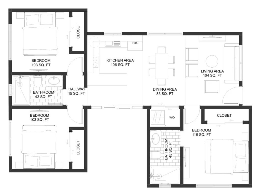
Solid black walls, thin-line windows, door arcs, room names, areas in square feet. No dimensions, scale bar or heights, so a model can only estimate scale from a door, a bed, or the areas.
The tool's own panel describes the output more precisely than any post.
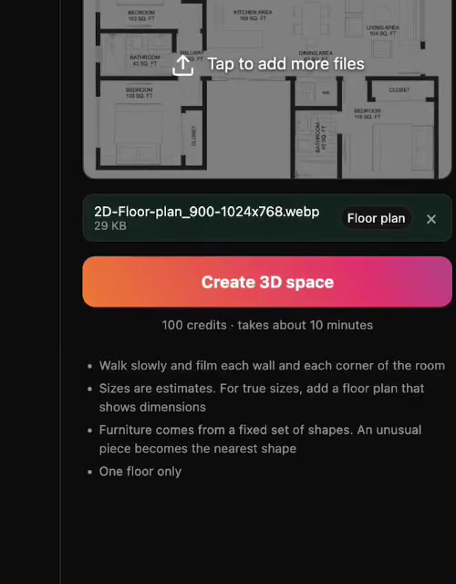
"Sizes are estimates. For true sizes, add a floor plan that shows dimensions." "Furniture comes from a fixed set of shapes." "One floor only." "100 credits · takes about 10 minutes." The "5 minutes on a VPS" that got quoted around belongs to his earlier walkthrough-video post, not to this one.
levelsio lists the misses himself: "the big I guess sliding windows to outdoor garden are missing, and bath tub is just a box, and I don't see a toilet seat etc." The sliding doors are drawn as thin lines in a gap of the wall band, the hardest thing on that sheet to tell from a window or from nothing.
What it produces. A mesh scene of one storey whose furniture you can move, delete and recolour. No storeys, wall types or element export, and no claim of any. Fine for redecorating a room; not BIM.
Where it would break. More than one floor, hatched or outlined walls, and area labels that disagree with the drawing (marketing plans count wall thickness in or out by market), which a model reconciling scale against them inherits.
The barn tool: a vector PDF, read without a model
Romain Briaux is a designer and co-founder of Hervé Studio in Paris. In July he posted that while making a tool for line-drawing illustrations for a client's airflow data visualisation, "I may gone a bit too far and created something a bit more advanced".
In the replies he says the furniture is parametric and the closing render is "chatGPT image 2 guided by the wireframe reference". The 13 November post is the same tool grown into a building editor, tested on his own barn.
It has no name or link yet; he says it is "Not public yet".
How walls get in. Asked about input, he replied: "Input was my architect's PDF plans, exported from Archicad. The tool reads the vector drawing directly (no AI): walls, doors, windows, stairs, plus the electrical and plumbing sheets. Walls land within ~1 cm of the drawing, so it's as accurate as the plans." Photos or sketches go through a model instead, "but those come out rougher". That is vector reading on an Archicad PDF, about the cleanest input there is.
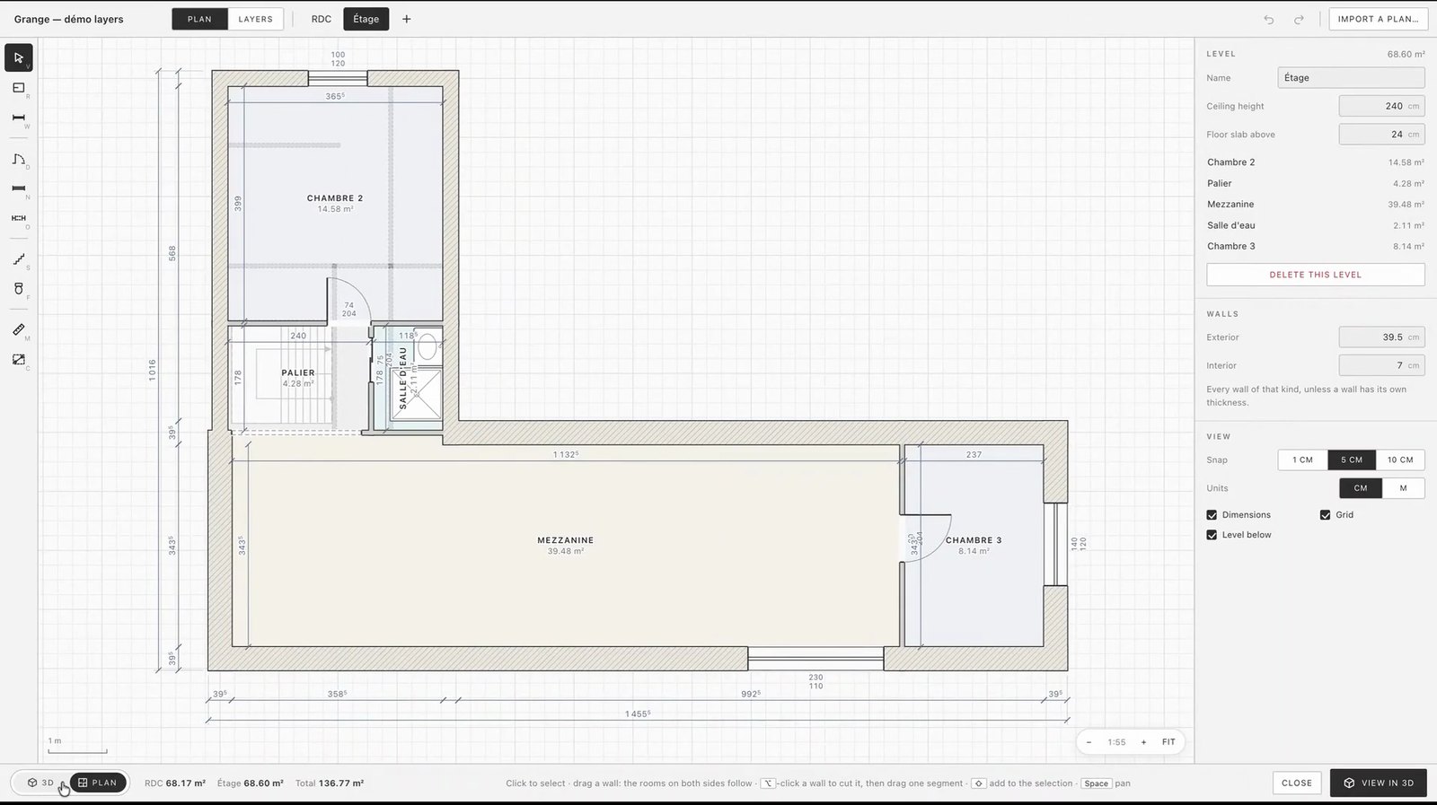
What the model holds. The plan view has storey tabs, RDC and Étage. A storey has a ceiling height (240 cm) and a "floor slab above" (24 cm). Walls default to an exterior thickness (39.5 cm) and an interior one (7 cm), "unless a wall has its own thickness". Openings are labelled the French way, width over height: 74/204 for a door, 100/120 and 230/110 for windows. Rooms carry areas (the Mezzanine is 39.48 m²). French plans write every opening's height on the plan, so this is the only tool in the set that can take it from the drawing instead of defaulting it.
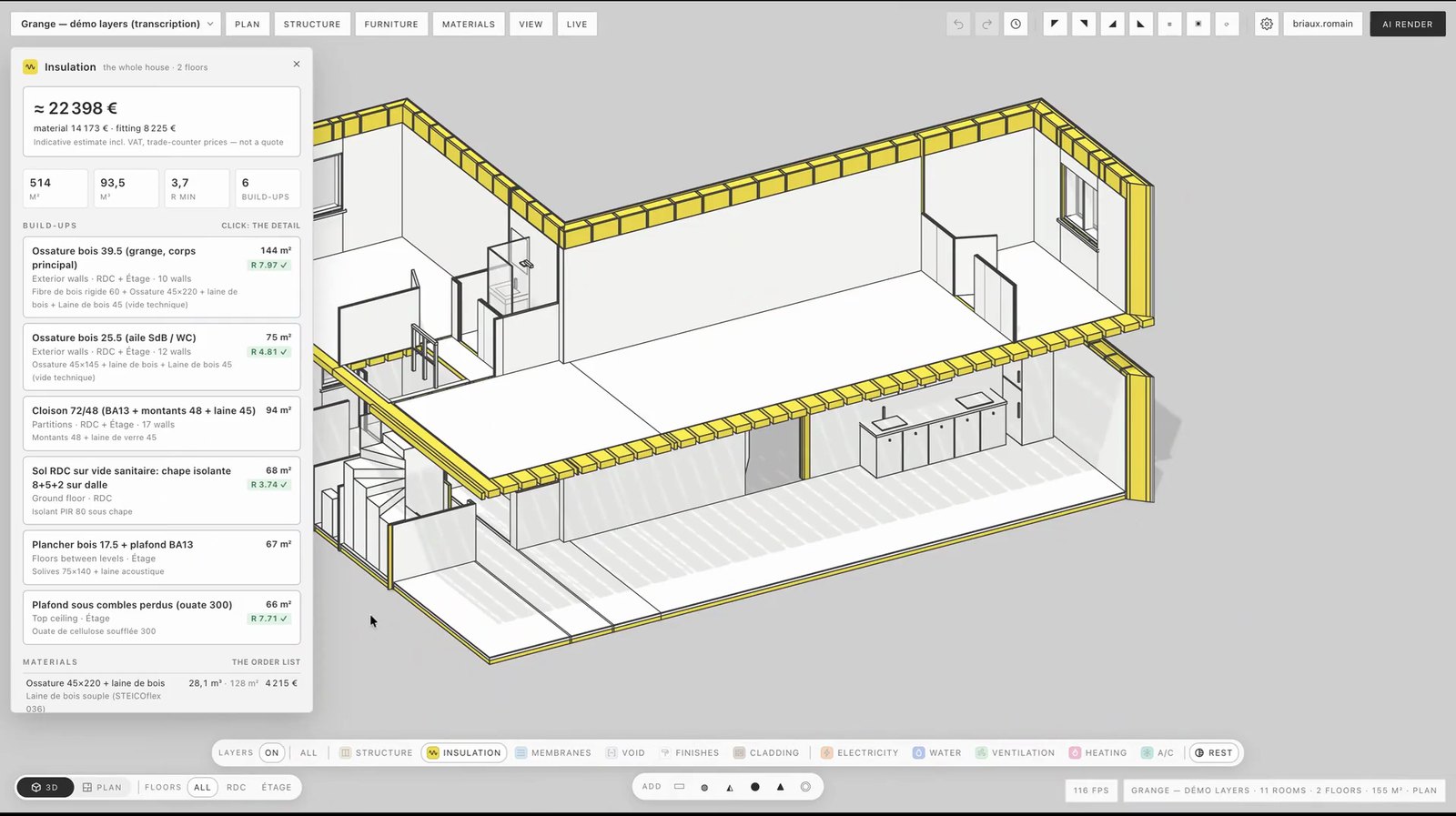
The insulation panel lists six build-ups. The main one is a 39.5 cm timber frame ("Ossature bois 39.5") with rigid wood fibre, a 45×220 frame filled with wood wool and a service void, over 144 m² of exterior wall, with an R value of 7.97. The panel totals about 22,398 € (14,173 € material, 8,225 € fitting) and labels it "Indicative estimate incl. VAT, trade-counter prices — not a quote". That is a material layer set in all but name: the thing IfcMaterialLayerSet exists to hold, and the thing none of the other three tools store.
What it lacks. Export: "No yet.. but soon". A question about IFC got no reply. The richest model of the four is locked in a tool nobody else can run.
Where it would break. PDFs from other tools. A generic print driver turns hatches into thousands of strokes and text into outlines, and a rule-based reader built on one architect's sheets will meet both. Sheets that disagree (an electrical plan on an older revision) arrive as clashes. For one barn and its own architect's PDFs, ~1 cm is as good as the drawings.
3d-new-era-ai: the one with source
3d-new-era-ai is a home design editor written in Rust, licensed MIT or Apache-2.0, that bills itself as "A Sweet Home 3D alternative" and ships an MCP server: "Claude, ChatGPT, Codex, Gemini, Cursor or any other MCP client draws the walls, furnishes the rooms, builds the joinery, checks lighting and ergonomics against real standards and renders the photos." There is a desktop app, a browser editor and a hosted connector. I cloned commit 81711b4 (2 November 2026) and read the core model, the MCP tools that touch walls, the tracer, the mesh builder and the exporter. By my count the crates hold 131,452 lines of Rust across 199 files. I did not run it.
Open-source home design and floor plan editor in Rust (a Sweet Home 3D alternative) with a built-in MCP server: your AI agent draws walls, furnishes rooms, checks lighting and ergonomics, and renders photos — live, on your own machine.
- license
- Apache-2.0
- branch
- main
- forks
- 19
- open issues
- 7
- source
- 5.4 MB
- commit date
- 2026-11-02
GitHub REST API, 2026-11-16 — branch, commit, commitDate, createdAt, description, forks, homepage, languages, license, openIssues, pushedAt, stars, topics
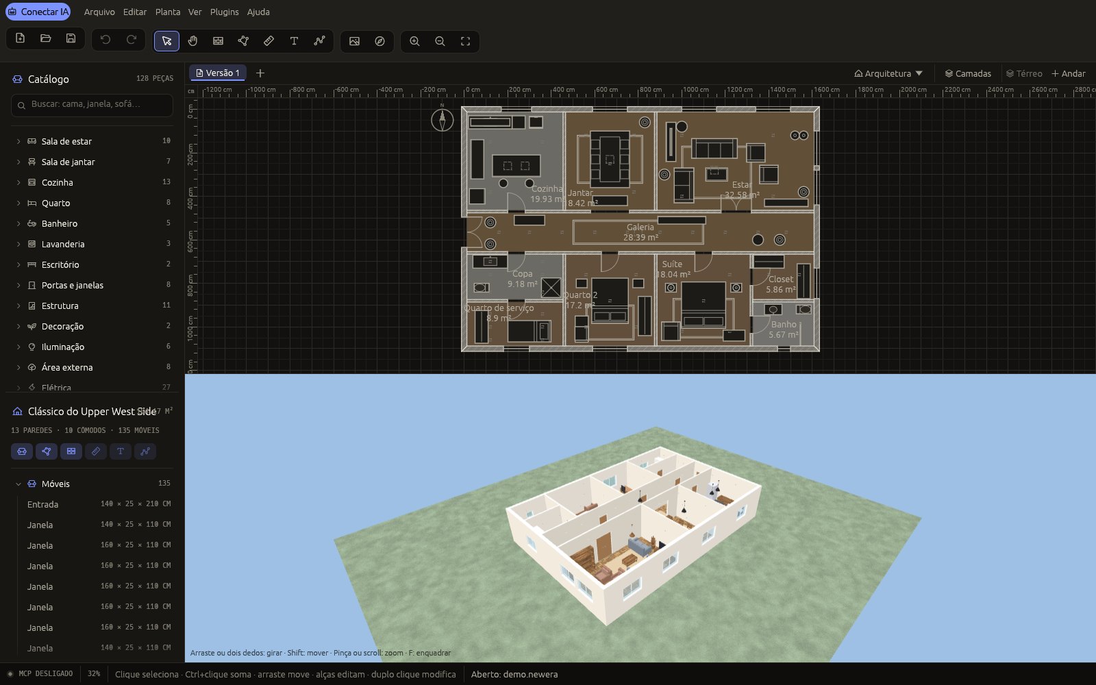
The data model is element-level
Every change is a Command executed by a Document, and "The desktop UI, the MCP server and the REST API are all just clients of that rule." A click and an agent's tool call share one undo stack; batches are atomic.
A Wall in newera-core/src/elements.rs has start, end, thickness and height in centimetres, an optional arc, an optional level, an optional wall_type, finishes per side, baseboards, and height_at_end for gable walls. A Level has elevation, height (default 250 cm) and floor_thickness (default 12 cm). Doors and windows are furniture pieces with an Opening (door, window or passage, with hinge side, leaves and sliding). Rooms are polygons with a name and a use.
That is a real building model, much closer to BIM than a mesh. It falls short of IFC in a few places.
Wall types are a name and a thickness. WALL_TYPES in materials.rs is a list like drywall-95, "Drywall 95 mm", with a thickness of 9.5 cm and a Portuguese description of the stud and boards. The layers are prose, not data.
Openings find their host at render time. wall_cuts in furniture.rs takes every door or window and cuts it into each straight wall it is aligned with (within 5°) and sits inside (within half the wall's thickness or the piece's depth, plus a centimetre). No door-to-wall relation is stored, so an exporter would have to recompute the host, and the first filter in that function, .filter(|(_, w)| !w.is_arc()), means curved walls never get holes. mesh.rs skips arcs the same way when it splits wall faces at openings.
Rooms are derived. detect_room in detect.rs unions all wall footprints and returns the hole containing a point: "Holes in the union of all wall footprints are exactly the enclosed rooms." That is how an agent creates a room by naming a point.
The tracer: dark bands, and nothing else
The MCP tool edit_background puts a scanned plan under the drawing at real scale (one or several known distances fit X and Y scales by least squares, in BackgroundImage::fit_scale) and, with action: "trace", turns it into walls. The tracer in newera-mcp/src/trace.rs says what it is in its first line: "thick dark bands running across or down the image become wall axes with their thickness. Good for orthogonal plans with filled walls."
Step by step, with the defaults from background.rs:
- Ink mask. A pixel is ink if its luminance is under 128 and it is not saturated, so "Humanized plans paint lawns, plants, furniture and cars in color; walls are black or gray."
- Bands. Scan every row for ink runs at least
min_lenlong (60 cm), and track runs that continue on the next row. Do the same down every column. A band whose stack of rows is betweent_minandt_maxthick (5 to 45 cm) is a wall; its middle row is the axis. - Snap. A horizontal wall's ends move onto the axis of a vertical wall they run into, and vice versa.
- Merge. Collinear pieces of similar thickness join if the gap between them is at most
max_gap, 130 cm. The comment in the tool schema: "Doors and windows up to this wide don't split a wall." - Clean. Drop short pieces that touch nothing, then keep only connected clusters whose total length is at least a fifth of the biggest one: "A house is one connected set of walls."
- Create. Each traced wall becomes a
Wallwith heighth, 250 cm by default, in one undo step.
Step 4 is right for topology (one wall, not two stubs) and it deletes the opening. The tracer never creates a door or window: openings up to 130 cm become solid wall the agent must cut again by placing a door, and wider ones leave a full-height void. The project's own test is named "colored_blobs_are_not_walls_and_openings_do_not_split_them".
I wanted to see that on a real plan, so I ported the tracer to Python (about 170 lines, following the Rust step for step, my code, not theirs) and ran it on levelsio's plan. That plan has no dimensions, so I set the scale at 1.3 cm per pixel from a door opening of about 60 pixels, assuming a 76 cm door. At the defaults the port finds 20 walls and bridges five gaps of 60, 61, 81, 92 and 92 cm. Those are door openings, now solid wall. With max_gap at 0 it finds 24.
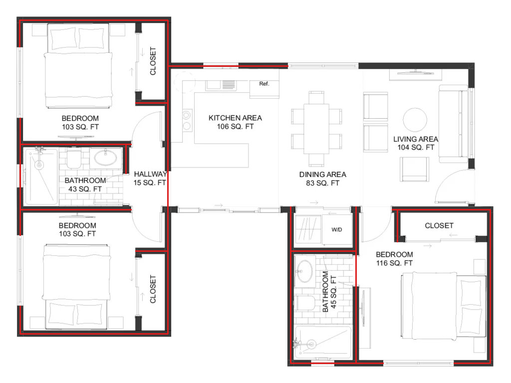
What is missing teaches more. The living room's top and right walls are not traced, nor the kitchen's lower wall with the sliding doors. They are mostly glass drawn as thin lines, so the band breaks into pieces too short to keep, or into a cluster cut off from the house that step 5 drops. Those are the walls Interior AI's model missed too.
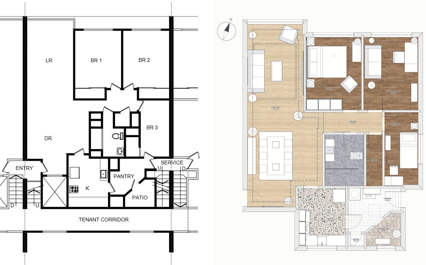
The repository's showcase suggests the authors know this. The README's 105 m² apartment was "traced from an openly licensed floor plan" of the FOCSA Building in Havana, and docs/SHOWCASE.md says how: the drawing has no dimensions, so the scale "came from things with known sizes (doors, toilet, cooktop): 2.4 cm per pixel", and the agent then called create with px: true and "coordinates read straight off the image (25 cm party walls, 12 cm partitions)". The agent typed the walls. It did not use the tracer. That took "About 60 MCP calls" for the whole apartment, furniture and lighting included.
What comes out
export writes a PDF, SVG or PNG plan, a GLB or OBJ model, and the joinery cut list as CSV or DXF. There is no IFC anywhere in the repository; I grepped. DXF appears only for cut-list sheets. And the GLB carries none of the element model: export.rs writes one node named "home" with one mesh, its triangles grouped only by material look. The wall ids, types, storeys and hosted openings exist inside the .newera project and stop at the export.
Where it would break. Non-orthogonal plans (the tracer sees only horizontal and vertical bands), hatched or outlined walls, multi-storey sets registered by hand one image at a time, and any handoff to a BIM tool. Inside its own world (a home furnished, lit, checked against cited standards and rendered) it is the most complete open tool for an agent I have seen. It is not a drawings-to-BIM tool and does not claim to be.
Side by side
| Snaptrude Agent | Interior AI 3D | The barn tool | 3d-new-era-ai | |
|---|---|---|---|---|
| Input shown | DWG sheets plus a long brief | a plan image | Archicad vector PDF | a scanned image, or .sh3d |
| How walls are found | agent on Snaptrude's tools; method not documented | a model writes a Blender scene | vector reading, "no AI" | dark-band tracer, or the agent types them |
| Openings | claimed as elements | sliding doors missed | read, with width over height | pieces cut into walls at render; tracer bridges them |
| Storeys and heights | from the prompt | one floor | per-storey settings | Level records, 250 cm default |
| Wall construction | claimed types | none | layered build-ups with R values | a name and a thickness |
| What comes out | claimed IFC 2x3 and IFC 4, native .rvt | a three.js scene | nothing yet | GLB or OBJ as one mesh, plans as PDF or SVG |
| Code | closed | closed | unreleased | MIT or Apache-2.0 |
What I would use, and for what
With a real DWG set due Friday, Snaptrude is the only one that claims the output I need. I would export its IFC first and check it the way I checked Mutiny BIM's with IfcOpenShell: count IfcWall and IfcDoor, check each door's IfcRelFillsElement, compare storey elevations to the section. Its brief shows the uncomfortable part. Someone typed the storey heights, the core rule and the work order. That is a modelling brief by a person who already understood the building, not "one prompt".
The barn tool is the one I would learn from: vector reading without a model, build-ups stored as layers, opening heights taken from the drawing. Give it an IFC writer and it is a useful small-building tool.
Interior AI is for looking, not building, and its own panel says so.
3d-new-era-ai is worth reading for its command model and MCP design notes. For drawings to BIM it lacks a vector reader, stored host relations for openings, and an exporter that keeps elements as elements.
All four share the gap the 3D and BIM tools roundup found from the scan side: the step to correct, typed, hosted elements is the thinnest, and the agent's guesses go unchecked there. The fix is not a better 3D view. It is reading the sections and schedules too, and saying for every height where it came from.
What I ran and what I read
I read the four posts, threads and quoted posts through the fxtwitter mirror and stepped through each video; Snaptrude's prompt and questions are transcribed from full-resolution frames, its claims from its site and help pages on 16 November. I read 3d-new-era-ai at 81711b4. The only code I ran is my own Python port of trace.rs, on levelsio's plan at an assumed scale. I did not run 3d-new-era-ai, Snaptrude's agent or Interior AI on my drawings, and the barn tool is unreleased. Related reading: the image-to-DWG skill, Mutiny BIM's IFC 4.3 export, measured, debim's YAML-to-IFC compiler, OpenTakeoff's scale gate, SpatialLM's scan-to-plan model and KOLC+ splats inside BIM.