An image-to-DWG agent skill, read: the model writes the drawing as JSON, a ledger tags every dimension, and AutoCAD draws it over COM
mdjsonmcp2026-11-13 · 26 min · cad · bim · agents · agent-skills · computer-vision
A 3:34 narrated explainer, drawn in code. Every number and picture in it is this article's own; the sources are below.
› transcript
A photographed sketch of a room. No source file. Somebody has to redraw it in AutoCAD, one line at a time. Hi, I'm Burl! This open skill promises to do it for you, and to say which numbers it guessed. I read every file. First, a quick check of the image: size, blur and contrast. Then the key step, and no script does it. The model looks at the picture and types the drawing as JSON. A validator checks the JSON's shape. Python drives AutoCAD over COM, one call per entity, and saves a DWG. A preview is rendered on a fixed page. Then the preview is laid over the source, to measure how far apart the lines are. Here is the one worked example in the repository. Five entities on a small part. Each value says where it came from. Read off the drawing, scaled from pixels, inferred, or unreadable. Take a small plan. The model redraws the walls and types every dimension. Two are printed on the sketch. Six thousand, and two thousand four hundred. Those are known. The rest are measured in pixels and scaled by an anchor, the nine hundred pixel overall width. The door is a guess at a standard size. The window's label is smudged, so it stays unreadable. Now misplace one end of the anchor by four pixels. The wall becomes three thousand five hundred and eighty-four, and the chain stops adding up. That ledger is the right idea. But the drawing script never reads it. In the DWG, every dimension looks the same. Here is the formula. The slip is how far off one endpoint is, in pixels. The span is how long the anchor is. A four pixel slip on nine hundred is about zero point four four percent. Every scaled length shares it. On a sixty pixel column, the same slip is six point two five percent. Here it is in the article's own widget. Slip the anchor by four pixels, and the scaled values drift while the chain check turns red. Calibrate on the short column instead, and the same slip throws every scaled length much further. Then look at the drawing AutoCAD gets. The colours are gone. Nothing in the file says which numbers were guessed. The check fits the redraw onto the sketch at four corners, then measures edge distances. An exact redraw sits right on top. Now make every length three percent too long. After the corner fit, it scores exactly like the perfect one. A wall in the wrong place does show. The ninety-fifth percentile jumps to thirty-eight pixels. A missing door shows only one way round, from the sketch to the redraw. Its own warning says the metrics assess registered visual linework, not physical dimensions or units. And the status it writes is always pass. So, the post's seven claims. Two hold as written: the drawing data, and AutoCAD drawing it. Five hold in part. Recognition is the model's, and the ledger stays in the JSON. For drawings to BIM, keep the tag on the element, so it survives the file. Diff every view against its sheet. It catches a wall on the wrong grid line. And check the scale against printed dimension chains, because the diff cannot. Read it as a specification. Tag every number by where it came from, and never let a picture that looks right stand in for a dimension. The model types the drawing, every value is tagged, and the check measures but never decides. Thanks for watching! Every source is in the full article. I'm Burl. Bye!
Why read this
Solidtop 85%Reads every file of an image-to-DWG skill, separates checks in code from checks in prose, and measures its redraw metric on chosen errors.
- Original analysis
- A lasting reference
- Concrete numbers to act on
Agents & harnessesRuns on a laptop CPUNo licencePractitioner teardown
How this was scored
- Is it new?
- 1 of 3: An incremental tweak
- Can I trust it?
- 2 of 3: Measures key facts from files, code or configs
- Can I run it?
- 1 of 3: API-only, gated or restrictive licence
- Will I understand it?
- 2 of 3: Mechanism from first principles with figures
- Can I act on it?
- 2 of 3: A concrete recipe, numbers or comparison
- Will it last?
- 2 of 3: A reference for a year or more
- Does it affect many?
- 1 of 3: A specialist community
- Only here?
- 2 of 3: A teardown or measurement few others did
Score 59 of 100, ranked 461 of 740 rated articles. Each question is answered 0–3 by hand, and a 3 is rare. How articles are scored
On 13 November the X user CY160909 posted, in Chinese, about an open-source skill that "can redraw hand sketches, scanned drawings, even CAD screenshots as editable DWG", and that "doesn't only draw, it also checks the redraw". The post lists what it does: recognise the lines, arcs and dimensions in a drawing; generate CAD drawing data; call AutoCAD to draw an editable DWG; organise layers and export DXF and a preview; compare against the original to check the deviation. Then the part the poster liked best, which I translate as: "which dimensions are explicitly annotated, which are scaled by proportion, which are only the AI's inference, and even which cannot be recognised at all, it handles each differently." The post ends with sensible advice: check the key dimensions by hand, and don't treat it as an engineering-grade conversion.
The repository is pengxiaoan/autocad-dwg-redraw-skill. I cloned it at commit ed182ec (11 July 2026) and read all of it: 21 files, 3,888 lines, of which 2,420 are Python and 1,429 are Markdown. I did not run it. It needs AutoCAD on Windows, and this piece was written on a Mac without either. What I did run is my own reimplementation of its comparison metric, on a plan I generated, so I could feed it errors I chose.
- branch
- main
- forks
- 66
- open issues
- 0
- source
- 96.4 kB
- commit date
- 2026-07-11
GitHub REST API, 2026-11-13 — branch, commit, commitDate, createdAt, forks, languages, openIssues, pushedAt, stars
Why a drawing is not a picture of lines
A raster drawing gives you pixels. A DWG wants entities: a LINE from one point to another, an ARC with a centre, radius and two angles, a DIMENSION whose definition points sit on the geometry it measures and whose text is computed from them. Getting from one to the other is four problems stacked on top of each other, and only the first is about lines.
Primitives. A pen stroke is a few pixels wide and wobbles. Fitting a line means picking its centreline, its ends, and whether two nearly collinear strokes are one wall or two. Arcs are worse: a short arc of large radius is almost a line, and a fit will happily return an arc for a sagging line or twenty segments for a quarter circle. Both look right at a glance.
Dimension text and what it belongs to. OCR can read "3000". It cannot tell you which two extension lines that 3000 spans, whether the arrowheads point inward or outward, or whether a 3000 next to a 1050 next to a 1900 is a chain or three overlapping dimensions. Association is the hard part, and it is layout reasoning, not character recognition.
Scale. A photo of a drawing has perspective. A scanned sheet has paper stretch. A sheet with a plan and a detail has two scales, and a sketch has none at all. To turn pixels into millimetres you need an anchor, a length you know, and the anchor's error flows into every value you measure with it. If the anchor spans pixels and you misplace an endpoint by pixels, the scale is off by
and every measured length is off by . A 4 px slip on a 900 px anchor is 0.44%, which is 19 mm on a 4,200 mm wall. The same slip on a 60 px column is 6.25%.
Constraints and stack-up. Drawings are full of relations nobody writes down: this wall is parallel to that one, this arc is tangent to that line, these three bays sum to the overall width. And errors add up along a chain. Independent reading errors of size on chained dimensions grow as , but a scale error is common to all of them, so it grows with the total length: . That is why one bad anchor is worse than many small misreads.
Classical vectorisation solves the first problem and declines the rest. Potrace traces the outline of each black region into Bézier curves; it is built for logos and glyphs, and on a drawing it returns two outlines per stroke rather than one centreline, with no idea what a dimension is. Centreline tracers (thin the strokes to a skeleton, then fit) and Hough transforms get you lines, and commercial raster-to-vector tools in the Scan2CAD mould add arc fitting and OCR on top. What none of them produce is a statement of where each number came from. A vectorised scan says "there is a line here, 3,012 units long". It does not say whether 3,012 is a reading of a printed "3000", a pixel measurement, or a guess.
That last statement is what this repository is about.
Two skills, written for Codex
The repo holds two skills, each a folder with a SKILL.md, references/, scripts/ and agents/openai.yaml:
| skill | input | what it does |
|---|---|---|
autocad-image-redraw | photo, scan, sketch, screenshot | model writes a JSON spec, scripts validate it, draw it in AutoCAD, inspect it, render a preview, compare with the source |
autocad-dwg-redraw | a DWG, or a PDF turned into one | profiles the DWG into a "redraw prompt", then copies its entities into a new drawing and compares counts |
Both target OpenAI's Codex. agents/openai.yaml is Codex's skill metadata (display name, short description, default prompt), the README installs through ~/.codex/skills/.system/skill-installer, and the two pull requests were opened from branches named codex/…. The SKILL.md frontmatter (name, description) is the same shape Claude Code reads, so the folder would load there, but nothing in the repo is written or tested for it.
The repository went up on 15 June 2026 and has 10 commits; the image skill, the one the post is about, arrived on 11 July with a Chinese tutorial (docs/图片自动绘制DWG使用教程.md, 474 lines) the same day. When I read the GitHub API on 13 November it showed 416 stars, 66 forks and no licence.
The model is the detector
Here is the image skill's pipeline, as the tutorial lays it out:
preflight_image_redraw.pyhashes the image, normalises EXIF orientation and computes three numbers: the grey-level standard deviation (contrast), the variance of the Laplacian (blur) and the fractions of very dark and very light pixels. It warns below 700 px on the short edge, below 18 of contrast and below 45 of Laplacian variance. Instrict-dimensionedmode it blocks without physical units or at least one anchor.- The model reads the image and writes
redraw-spec.json. There is no script for this step. The tutorial says it plainly: "通常由 Codex 根据图片生成", usually Codex generates it from the image. validate_image_redraw_spec.pychecks the JSON.draw_image_spec.pydraws it through AutoCAD's COM interface and saves a DWG.inspect_dwg_output.pyreopens the DWG and counts what is in it.- You save the DWG as DXF in AutoCAD by hand;
render_dxf_preview.pyaudits the DXF with ezdxf and renders it to a fixed A3 page at 300 dpi. compare_redraw.pyregisters the preview onto the source and measures edge distances.
So the post's first claim, that it "recognises the lines, arcs and dimensions", is true only in the sense that a vision-language model looks at the picture. No Hough transform, OCR engine or arc fitter runs in the main path; every coordinate in the DWG is a number the model typed. That is a reasonable bet in 2026, since association is layout reasoning and that is what a vision-language model is for. It also means the skill is only as good as the model, and the scripts can check its output for consistency, never for truth.
There is a separate script that does detect, image_to_dxf_open_source.py, offered as a rough path for people without AutoCAD. It thresholds at grey level 150, runs OpenCV's probabilistic Hough line detector (minimum length 22 px), snaps lines within 1.5° of the axes, optionally finds circles, and traces contours into polylines. It finds no arcs and reads no text, and its docstring says so: "a visual vectorization pipeline, not a semantic mechanical drawing parser." It also writes the DXF in millimetres at a default of one unit per pixel, so a 1,000 px screenshot becomes a drawing a metre wide, which is exactly what the image skill's own SKILL.md forbids: "Do not default to millimeters merely because the drawing looks technical."
The spec, and the four evidence levels
The spec is version 2.0 of a JSON format documented in references/image-redraw-spec.md. Its top level is metadata (title, units, profile, source image), an optional source block (hash, pixel size, perspective, occlusions), views, calibration, constraints, layers, entities and validation. Counted from the spec and its validator:
- 13 entity types:
line,polyline,rectangle,circle,arc,center_mark,text,mtext,leader,linear_dimension,aligned_dimension,radial_dimension,table. Coordinates are CAD units, never pixels; angles are degrees in the spec. - 6 units (
unitless,mm,cm,m,in,ft) and 5 profiles:strict-dimensioned,general,hybrid,visual-trace,geometry-only. - 5 calibration methods:
dimension-anchor,affine,homography,sheet-scale,visual-only. A calibration records its source pixels and the CAD points they map to, so the scale is evidence you can audit rather than a single number. - 4 evidence levels, which any entity, calibration or constraint can carry, with an optional
confidencefrom 0 to 1 andsource_refspointing at the readings it rests on:
| level | meaning, from the spec |
|---|---|
known | directly stated by the user or legible in the source |
scaled | measured after a documented calibration |
inferred | derived from symmetry, continuity, layout, or engineering judgment |
unreadable | visible but not reliably decipherable |
Unreadable text is written as [UNREADABLE] and keeps its location. The SKILL.md adds an authority order for when values disagree: explicit user requirements, then readable dimensions, then derived constraints, then calibrated measurements, then labelled visual estimates. And a rule I would put on a wall: "Do not silently choose between conflicting dimensions. Record the conflict and return needs_review or blocked."
The only worked example in the repository is references/minimal-example.json: five entities on a 120 by 60 mm part. I drew it with my own script, coloured by evidence level.
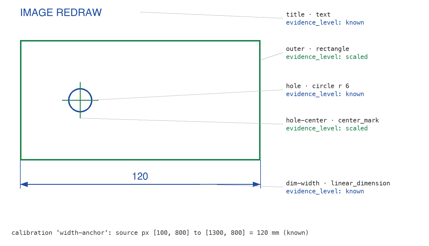
This is the idea the post found most interesting, and it is the right one. A redraw from a picture mixes four kinds of number with very different reliability, and a DWG flattens them: once drawn, a guessed door width and a printed overall dimension are the same kind of object. Keeping the ledger means a reviewer checks the scaled and inferred values and leaves the known ones alone, and a downstream tool can refuse to quantity-survey anything that is not known. The widget below is a small plan with each dimension tagged. Move the anchor's endpoint and watch which values move.
Scaled values move together, because they share one scale; known and inferred values do not move at all. And the chain check is what catches the bad anchor: with a 4 px error on the 900 px overall-width anchor, the scaled wall position comes out at 3,584 against a derived 3,600, the chain (3,584 plus the printed right bay of 2,400) sums to 5,984 against a printed 6,000, and the spec's own sum constraint with its 1 mm tolerance fails. Calibrate on the 60 px column instead and the same 4 px slip puts the depth at 3,938 mm, more than 260 mm short. Long anchors, many anchors, and a chain to check them against.
What the scripts enforce, and what only the prose asks for
This is where the post oversells, and where a reader building something similar should look hardest. The ledger is a documented convention. Very little of it is checked in code.
The validator checks the enum and the range, not the rules. validate_image_redraw_spec.py rejects an evidence_level that is not one of the four words, and a confidence outside 0 to 1. It does not require an evidence level on anything, even in strict-dimensioned mode. The validation reference promises a check for "no unreadable value used as a solved dimension" and a calibration per view; neither is in the script. Strict mode requires units other than unitless and at least one calibration in the whole file that is known or scaled and has a value or two points.
Constraints check arithmetic on numbers the model typed. The three numeric constraint types are sum, difference and equality, and their terms are literal numbers, not references to entities. A constraint {"type": "sum", "terms": [3000, 1050, 1900], "expected": 5950} passes whatever the drawn walls measure. The spec says so: geometric relations "such as tangency or concentricity" stay "descriptive constraints until a domain-specific checker is available", and the validator turns any other type into a warning. So the check proves the model can add, which is not nothing (models misread a 5 for a 6), but it does not tie the numbers to the drawing.
Dimension text is overridden. draw_image_spec.py creates a dimension with AddDimRotated (or AddDimAligned, AddDimRadial) from the spec's p1, p2 and dimline, then, if the spec has a text, sets TextOverride to it. An associative dimension's whole point is that its text is measured from its definition points. With an override, a dimension can read "3000" over geometry that measures 2,950, AutoCAD will display it without complaint, and nothing in the repository compares the two. In a hand-drafted shop that is a known sin; here it is the default whenever the model writes a label.
The ledger never reaches the DWG. draw_image_spec.py does not read evidence_level at all. It does not map evidence to a layer, a colour or extended entity data. The spec's recommended ASSUMPTION layer exists only if the spec lists it, and the renderer's eight default layers (OBJECT, HIDDEN, CENTER, DIM, TEXT, TABLE, CONSTRUCTION, BORDER) do not include it; the reference recommends twelve, adding STRUCTURE, WINDOW, DOOR and ASSUMPTION. Open the DWG a month later and a guessed dimension looks exactly like a printed one. The provenance lives in a JSON file beside the drawing, and files beside drawings get lost. The "as drawn" view in the widget above shows what is left.
None of this makes the design wrong. It makes it a specification with partial enforcement, and the post's "it handles each differently" should read "it asks the model to label each differently".
Driving AutoCAD
The drawing step is plain COM automation through pywin32, with no AutoLISP, no script file, no accoreconsole and no ezdxf on the DWG path. get_autocad tries, in order: binding through a named document with GetObject (a workaround for AutoCAD's Start page confusing COM), a fresh instance with DispatchEx when asked for one, the running instance with GetActiveObject, launching acad.exe and polling for 45 seconds, and finally Dispatch. Points go over as VARIANT(VT_ARRAY | VT_R8, (x, y, z)). Each entity type maps to one ModelSpace call:
line              AddLine
polyline          AddLightWeightPolyline   (closed by repeating the first point)
rectangle         AddLightWeightPolyline
circle / arc      AddCircle / AddArc       (degrees converted to radians)
text / mtext      AddText / AddMText
linear_dimension  AddDimRotated            (+ TextOverride)
aligned_dimension AddDimAligned            (+ TextOverride)
radial_dimension  AddDimRadial             (+ TextOverride)
leader            AddLine per segment + AddText
table             AddLine grid + AddText per cell
center_mark       two AddLine
Two of those are downgrades a CAD user will notice. A leader becomes loose lines and a text, not an AcDbLeader, and a table becomes a grid of lines and text, not an AcDbTable. If a dimension call throws, add_dimension_fallback draws a line between p1 and p2 and a text at the dimension line: something that looks like a dimension and is not one. Units go into INSUNITS (0 unitless, 1 inches, 2 feet, 4 mm, 5 cm, 6 m) with LUNITS set to decimal. Text gets a style named CN_TEXT pointed at the first Chinese-capable Windows font it finds (SimHei, SimSun, Microsoft YaHei, Noto Sans SC, Arial Unicode), which is the kind of detail you only write after a drawing full of question marks. Creating the document is retried 60 times at 0.5 s, because AutoCAD answers "call was rejected by callee" while it is busy; the entity calls are not retried, and one failure stops the drawing with the entity's index.
apply_props sets layer, colour and linetype inside try/except: pass, so a layer name the spec forgot to declare fails silently and the entity stays on layer 0. inspect_dwg_output.py would then report the required layer as empty, which is the right place to catch it.
The post's "exports DXF" is half true. The image skill's draw script saves only the DWG; step seven of the tutorial is "在 AutoCAD 中把 DWG 另存为 DXF", save it as DXF in AutoCAD. Only the rough open-source tracer and the PDF path write DXF directly, through ezdxf.
The check that always passes
compare_redraw.py is the "compares against the original" claim. It needs an anchors file of at least four corresponding points, picked in the source image and the CAD preview; the tutorial asks for four or more, spread near the edges of each view, and allows one set per view for multi-view sheets. Then:
- Fit a homography from CAD points to source points with RANSAC (4 px reprojection threshold), warp the preview onto the source, and paste each view's region into a composite.
- Run Canny edge detection (thresholds 60 and 180) on both.
- Distance-transform each edge map and read, for every CAD edge pixel, the distance to the nearest source edge, and the reverse.
- Report the median and 95th percentile each way, and the share of edge pixels within 3, 5 and 10 px.
- Write a side-by-side, the registered CAD, a 60/40 overlay, an edge-difference image (source edges red, CAD edges blue, both green) and
metrics.json.
metrics.json contains "status": "pass", hard-coded, and "metric_scope": "visual_registration_only", with a warning that the numbers "assess registered visual linework, not physical dimensions or units". No threshold is compared to anything. The reference document calls the pixel thresholds "advisory". The decision is the agent's, reading the numbers and the pictures.
The scope note is accurate, and the reason matters. I wrote my own version of those five steps (same Canny thresholds, same distance transform, same statistics, my code) and ran it on a plan I generated: a 6,000 by 4,200 mm room drawn with wobbly 3 px strokes, photographed slightly off-square at 0.15 px per mm, and four CAD redraws of it registered on the four outer corners.
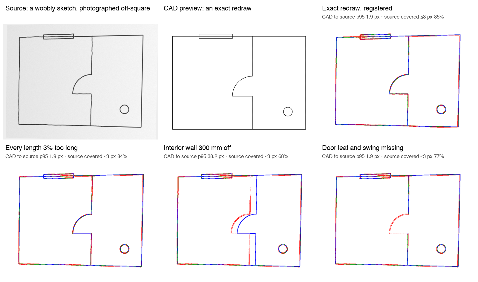
What it measured:
| redraw | CAD to source, p95 | source to CAD, p95 | source edges within 3 px | within 10 px |
|---|---|---|---|---|
| exact | 1.9 px | 3.8 px | 84.6% | 100% |
| every length 3% too long | 1.9 px | 3.8 px | 84.4% | 100% |
| interior wall 300 mm off | 38.2 px | 39.1 px | 67.8% | 84.0% |
| door leaf and swing left out | 1.9 px | 70.2 px | 76.5% | 92.2% |
A redraw that is wrong everywhere by the same factor is invisible: the homography maps the redraw's corners onto the sketch's, which is exactly the correction that hides a bad scale anchor, and 3% of 6,000 mm is 180 mm. A local error shows, because registration cannot move one wall without moving the rest. And the two directions are not redundant. An omission leaves every CAD edge on top of a source edge, so CAD to source stays at 1.9 px; only source to CAD sees the hole. The repository computes both, which is right, and leaves their interpretation to the model, which is where I would want a threshold.
The exact redraw's 3.8 px source-to-CAD p95 is the sketch's wobble. With the wobble turned off, the same run gives 1.9 px both ways and every source edge within 3 px; that remaining 1.9 px is Canny's, since a 3 px stroke has two edges on either side of the CAD's single thin line. Any threshold has to sit above that floor, and the floor moves with the hand, the pen and the resolution.
The widget lets you push the same errors. Here distances are exact point-to-segment distances on centrelines, so there is no double edge.
The anchors are also picked by the same agent that drew the redraw. If its reading of a corner is off, the registration bends to agree with it. That is not a flaw you can fix with more metrics; it is why the repository keeps saying the comparison "cannot prove real-world size". The check that can is a dimension chain tied to entity geometry, and that one does not exist yet.
The other skill copies
Given a DWG, dwg_prompt_builder.py opens it over COM and writes a Markdown "redraw prompt": file size, ModelSpace and PaperSpace entity counts, object types, layers with colour, linetype and lineweight, text and dimension styles, block names, and a classification from block names alone (a block with BOM or BILL in its name means an assembly; A0 to A3 or TITLE means a layout sheet; any dimension means a detail drawing). Then dwg_redraw.py does the "exact redraw": it collects every entity in the source's ModelSpace and PaperSpace, calls CopyObjects into a new document, and checks that the counts per ObjectName match.
That is a copy, and its validation compares a copy's counts with its original's, so it passes whenever CopyObjects works. The skill's SKILL.md also describes a third mode, "image + metrics": take a reference image plus a table of authoritative dimensions, generate AutoLISP or COM geometry, and optionally build 3D solids. It ships no code for that mode; it is instructions for the model. So "no AutoLISP" and "2D only" describe the scripts in the repository, not everything the prompt asks a model to try. The PDF route (pdf_vector_to_dxf.py) is more interesting: it reads vector paths from a PDF page with PyMuPDF, turns l into lines, re into rectangles and each cubic Bézier into 12 straight segments, and writes DXF in millimetres at one unit per PDF point by default (a point is 0.353 mm, so a scale has to be passed). Text in a vector PDF is often outlined, and the script keeps filled outlines unless told not to, so dimension text arrives as shapes.
One operational warning. --restart-autocad runs taskkill /IM acad.exe /F, which force-closes every AutoCAD process on the machine, unsaved drawings included. Run it on a box where nobody else is drafting.
Holding the post to the code
| claim in the post | what the code does |
|---|---|
| recognises lines, arcs and dimensions | the model does, by looking; no detector or OCR runs in the main path |
| generates CAD drawing data | yes: the model writes a JSON spec of 13 entity types, which a validator checks for shape |
| drives AutoCAD to draw an editable DWG | yes, over COM with pywin32; leaders and tables come out as lines and text |
| organises layers | 8 default layers created; the spec's 4 trade and assumption layers only if listed |
| exports DXF and a preview | preview yes (ezdxf, fixed page); DXF is a manual save in AutoCAD |
| compares with the original to check deviation | yes, edge distances after a hand-anchored homography; status is always pass |
| tracks where each dimension came from | in the JSON spec, as a convention; checked only for spelling, and dropped from the DWG |
Two of the seven hold as written: the drawing data and the AutoCAD step. The comparison exists but decides nothing, so I count it with the other four that hold in part.
And the housekeeping. There is no LICENSE file and the GitHub API reports no licence, so "open source" here means "public": by default nobody has the right to reuse it. There are no tests. The only example is the five-entity JSON above; there is no sample image, DWG or comparison output in the repository or its history, and .gitignore excludes *.dwg and *.mp4. The first pull request's description lists a preflight of an "existing hand-drawn plan" and an AutoCAD inspection that "passed with 264 ModelSpace entities". Those are the only traces of real runs, and neither input is included.
What a drawings-to-BIM pipeline should take from it
The same problem sits at the front of Satya Revit AI: a chat pane docked inside Revit plus an MCP tool server, so Claude Code or Codex can read and edit a live model, used to take 2D drawing sets to quantity-ready Revit models (the agent BIM tools roundup compares that route with one through IFC). Every wall placed that way starts as a number read off a sheet, and this repository has ideas that belong in that loop.
The ledger, carried on the element. Every placed element should say whether its length, height and offset were read off a dimension, scaled from a sheet, inferred from a type or a grid, or unreadable. The repository's mistake is keeping that beside the model rather than in it. In Revit it would be a shared parameter per element (or per driving dimension), in IFC a property set; either way it survives the file being opened by someone else, and a schedule can list every inferred wall before anyone orders steel. The authority order matters as much as the tags: a printed dimension never loses to a scaled one, and a conflict is a review item, not a silent average.
Redraw and diff, per view. Export the plan view the model produces, register it onto the sheet it came from, and diff. The experiment above says what that catches (a wall on the wrong grid line, a missing door) and what it cannot (a bad scale, because registration hides it). So the diff is a smoke detector for omissions and misplacements, run on every view, and the scale is checked separately against printed dimension chains bound to element geometry. In Revit that binding is natural: a wall's length is a parameter, and "the three bays sum to the printed overall" is a check on parameters, not on numbers the model typed.
Anchors as evidence. A calibration is a record (which two points, which printed value, which view), not a scale factor. Prefer long anchors and several per view, and check each one against a dimension chain before measuring anything with it.
Where it stops is equally clear. It is 2D only: lines, arcs and text, with no walls, doors or rooms, so a wall is two parallel lines with nothing that says they are one wall, and a door is an arc. It needs AutoCAD on Windows. And its semantics end at layer names. Getting from "two lines on layer STRUCTURE" to a wall type with a thickness and a level is the whole of the BIM problem, and it is what MutinyBIM and debim model with element records and what Construct does for objects with named parts. Each has its own gap between the check that runs and the property it should establish: debim's fidelity score passes an empty frame, and nobody checks Construct's hinges. Steve solves sketch constraints with FreeCAD's planegcs, the kind of domain-specific checker this spec says it lacks.
Where I land
Read it as a specification, not a tool. The image-redraw-spec.md and image-redraw-validation.md documents are the best short statement I have seen of how an agent should redraw from a picture without lying about it: evidence levels, an authority order, calibration as a record, separate profiles for "looks right" and "is right", and a refusal to let visual similarity stand in for dimensions. I would put their rules into any drawing agent's instructions.
The code is thinner than the post suggests. Recognition is the model's. The ledger is checked for spelling, and AutoCAD never sees it. Dimensions are overridden text over typed coordinates. The comparison measures something real and decides nothing. With no licence you cannot legally build on the scripts anyway. The poster's own advice stands: check the key dimensions by hand. I would go one step further and say which ones: every value the spec marks scaled or inferred, and every dimension whose override text was typed in.
What I ran and what I read. I read every file at commit ed182ec, both pull requests and the commit list through the GitHub API, and the post. I did not run any of the repository's scripts. The figure of the example spec is my drawing of its JSON; the comparison numbers come from my reimplementation of compare_redraw.py's steps (OpenCV 5.0, NumPy 2.5) on a sketch I generated, and the widgets compute their numbers in the page.